Generic HD44780 LCD Setup
|
This is a guide on how to set up a HD44780 compatible display for use with CrystalControl2.
|
If you have a 40x4 HD44780 LCD module, please see this guide. |
Doing so requires some electronics knowledge, a soldering iron and about 45mins of your time. |
The information in this guide is accurate, if your LCD does not work after completing the instructions here then either you have made a mistake, or your LCD module is faulty. |
|
|
Using a standard non-usb printer cable for the LCD cable to the PC is the easiest and quickest way to get a HD44780 based LCD working. |
You can use any other cable (such as ribbon cable), but you wont find instructions on how to use that cable in this guide. |
First, it is important that the printer cable does not have moulded connectors. The type of printer cable that needs to be used here will have "shells" encasing the back of each of the two plugs on the cable. |
The shells on the back of the plugs on both ends of the cable will need to be removed. They should either be held together with small screws or plastic clips. |
Once the shells are off, you need to identify the "Centronics" style connector end of the printer cable. The Centronics connector is the one that normally plugs into the back of the printer. This will be the end of the cable which will be modified to connect to the LCD module. |
As carefully as possible, heat each wire connection with the Centronics connector with the soldering iron, and remove the wire. Doing this will allow you to reuse the ends of the wires which will avoid you needing to strip and tin them. |
| If this cannot be done without damaging the ends of the wire, using wire-cutters, cut the wires from the connector as close as possible to the connector. If this is done, you'll have to then strip the ends of the wires and tin them. Only strip a couple of millimeters of insulation off the ends at the most. |
|
|
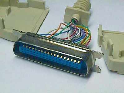
Centronics connector (printer end of the cable) with the shell removed. |
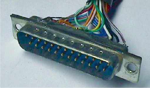
DB25 connector (PC end of the cable) with the shell removed. |
|
|
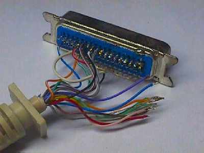
Centronics connector with some of the wires unsoldered. |
|
|
Your LCD should have either 16 or 18 connection holes (we'll call them pins) for the soldering of the wires. |
If the LCD is backlit, it will have either 16 pins with 2 pins at the other end of the LCD, or 18 pins in the same place. Those extra 2 pins are used for the backlight power supply, Step 5 will show how to connect these. |
If the LCD isn't backlit, it should only have 16 pins. If it has 18, disregard the last two (pins 17 and 18). |
|
|
This is the difficult bit of the project and will be the most frustrating. Take your time, and get it right the first time. |
The easiest way to describe how to connect the wires, is to give an example. This is an example for pin 1 on the DB25 connector. |
| |
Find pin1 on the DB25 connector. The pin number is normally printed somewhere on the plastic holding the pins in place. |
Remember the color of the wire connected to this pin (remember a wire can sometimes have two colors). |
Find the corresponding color wire at the LCD end of the printer cable. |
Solder this wire to pin6 on the LCD. |
|
This method of connecting the wires is then continued with the rest of the pins on the table below. |
| DB25 connector Pin Number |
LCD Pin Number |
LCD Pin Description |
| 1 |
6 |
Enable |
| 2 |
7 |
Data 0 |
| 3 |
8 |
Data 1 |
| 4 |
9 |
Data 2 |
| 5 |
10 |
Data 3 |
| 6 |
11 |
Data 4 |
| 7 |
12 |
Data 5 |
| 8 |
13 |
Data 6 |
| 9 |
14 |
Data 7 |
| 14 |
5 |
Read/Write |
| 16 |
4 |
RS |
| 25 |
1 |
Ground |
| 13 |
2 |
+5V |
|
| |
|
Printer port cables soldered to the LCD. |
|
|
Pin 3 on the LCD is used for contrast control. There are two options which can be taken in this step. |
The first option which is the easiest is to fix the contrast at a certain level. This is a bit of a gamble as the contrast setting may not be to your liking, but in most cases, the LCD contrast is set at an acceptable level. To do this, simply solder a piece of wire from pin 1 to pin 3 on the LCD. If you do this, skip to the next step of this guide. |
The second option is to connect a potentiometer (or "pot") to the LCD which will allow the LCDs contrast setting to be changed. |
There are two types of pot's which can be used for this, a normal full size pot, or a "trim-pot". I would recommend using a trim-pot, as its small, and if your clever can be mounted on the back of the LCD itself. The value of the potentiometer will need to be 10KOhms. It can be of either the "linear" or "logarithmic" variety, it wont make a difference. |
Solder a wire from the center pin of the pot, to pin 3 on the LCD module. |
Solder a wire from either of the two remaining pins on the pot to pin 1 on the LCD module. |
| Solder a wire from the remaining pin on the pot to pin 2 on the LCD module. |
|
|
If you do not have a backlit LCD, continue to the next step. |
Two components will be needed for this step, a resistor of a value you'll have to calculate, and a 100ohm potentiometer or trim-pot. |
The resistors value will need to be calculated first. To do this, you will need the LCD's specifications which should be available from the manufacturer of the LCD module. |
You'll need to know the recommended voltage required for the backlight and the current. |
Then using the following calculation, work out the resistor value needed: |
R = (5 - volts) / current |
For example, if your LCD required 4.2V at 400mA it would work out to be: |
R = (5 - 4.2) / 0.4 which makes R=22.5ohms |
If you cannot work out what the current is in decimal, use the following as a guide: 350mA=0.35, 100mA=0.1, 50mA=0.05, 10mA=0.01, etc. |
Now, solder one lead of the value resistor you calculated to the center pin of of the potentiometer or trim-pot. |
You'll now need to identify the connection points on the LCD for the backlight supply. |
If the LCD has 16 pins together, then the 2 unused pins should supply the backlight. They should also be labeled, if not, check the manufacturers data-sheet for the LCD. |
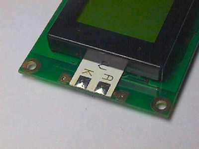
If the LCD does not have 16 pins together the connector pins for the backlight should be located at one of the ends of the LCD. The pins are normally labeled "A" and "K" or possibly "+" and "-". |
Now solder a wire from the "K" or "-" backlight supply pin, to pin1 on the LCD. |
Solder one lead of the value resistor you calculated earlier to the center pin of of the potentiometer or trim-pot. |
Solder a wire from pin2 of the LCD to the other remaining lead of the resistor. |
Solder a wire from either of the two remaining pins on the potentiometer or trim-pot to the "A" or "+" backlight supply pin. |
|
A typical LCD backlight wiring point. |
|
|
To power the LCD and the LCD's backlight, the DB25 connector end of the cable will now need to be modified. |
You will need to obtain a male "molex" connector. If possible, with wire already attached to it. |
A molex connector is the style of connector that is used to connect the power to hard-drives and cdrom-drives in your PC. |
Male molex connectors can be difficult to find, large electronics shops should stock them as well as some PC repair shops. Another source of male molex connectors is some brands of CPU fans. |
Solder a moderately long piece of black wire from pin 24 of the DB25 connector. |
Cut the wire on pin 13 as close as possible to the DB25 connector then strip the end of that wire. Solder a red wire (same length as the black), to the wire that was just cut from pin 13 and insulate it with insulation tape or heat-shrink tubing. |
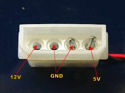
You now must make 100% sure you get the next few instructions right. If you do not, there is a big chance you'll destroy the LCD module and possibly some of your PC's hardware. |
Use the next image to identify the 5V and ground connectors on the male molex connector. |
|
Now solder your red wire to the 5V wire/pin of the male molex connector. |
Then solder the black wire to the ground wire/pin of the male molex connector. |
|
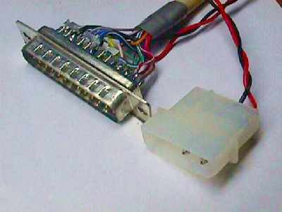
The DB25 connector with the power supply molex connector wires soldered in place and insulated. |
If it will still fit, it is a good idea to re-fit the DB25's shell to protect the wires on the back of the connector from damage. |
|
|
| Now, connect the LCD cable to the PC's printer port, and plug the male molex connector into a free power connector in your PC's case. |
| Power up your PC. |
| If completed, adjust the contrast control potentiometer until 1 row (or possibly 2 rows depending on the size of the LCD) of dark blocks can be seen on the LCD. |
| If your LCD has a backlight, adjust the backlight potentiometer until the backlight is at an acceptable level. |
| If the row/rows of black blocks are visible on the LCD, your power supply wiring and contrast control have been set up successfully. |
| The black blocks show that the LCD is ready to accept data from your PC. |
|
|
| 90% of problems with setting up a HD44780 LCD will be caused by a problem with the cable wiring. |
| If you have problems getting your LCD module to work, the first thing to do is check over all the wiring on both ends of the LCD cable. |
| If you can still not find anything wrong, get someone else to check your work over. A fresh pair of eyes, always helps. |
| Next step is to ask about your problem in the Crystalfontz internet forums. |
|
|