ZIF Connectors: Everything You Need to Know
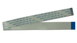
There are two main ways a display can be connected to a PCB. Some displays are solder-down, requiring fine pitch soldering to connect the tail to the contacts on the PCB. Others use Zero Insertion Force (ZIF) connection. With a ZIF connection, the tail of the display is simply slid into a connector. The tail should slide easily into the connector, thus “zero insertion force”. The connector has a movable piece that either swings down or pushes in, locking the tail in place.
Choosing a ZIF connector: what’s important?
In order to make sure the connector is compatible with a ZIF tail there are four features that need to be considered: Pins, Pitch, Connection Side, and Metal.
Pins
The need to consider pins in selecting a connector is fairly self explanatory: the number of pins on the ZIF connector should match the number of pins on the tail of the display. If the connector is too small, the tail will not fit. If the connector is too large, seating the tail can be confusing, plus the connector will take up more space on your PCB than necessary.
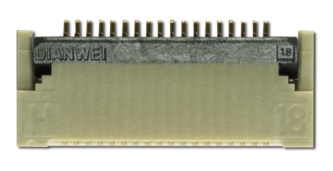
Pitch
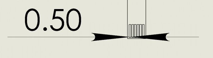
The pitch is how far apart the individual pins are on the tail. Crystalfontz carries displays with three pitches. The most common pitch is .5 mm, some displays with more pins to fit on the tail use .3 mm, and some tails (usually the touch panel tails) use 1 mm spacing. It’s very important to make sure the selected connector has the same pitch as the tail, otherwise adjacent pins can be shorted together causing irreparable damage to the display.
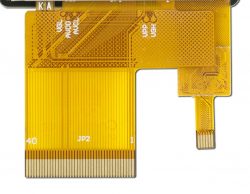
Connection Side
Connection side refers to which side of the connector has contacts. Some only have contacts on the top or bottom, while some have contacts on both. When selecting a connector, consider which side of the tail the contacts are on, and the orientation of the display to the PCB. Designs may require the tail to be folded, changing the orientation between the display and board.
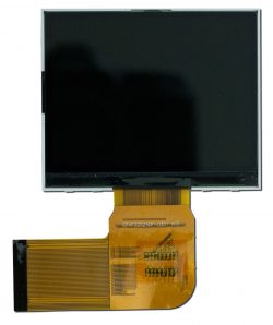
Some displays have pins on the opposite side from the active area 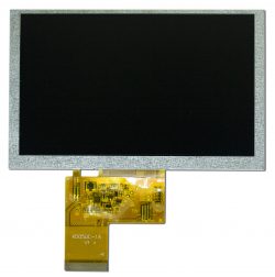
Others have pins on the same side as the active area
Metal
Finally, consider the metal used in the connector. Tin and gold are both commonly used. Tin tends to be less expensive, but does not last as long as gold. Over time, tin corrodes causing whiskering which can result in short circuits between pins. Due to this issue, tin is not typically recommended for any pitch finer than 1 mm.
Additionally, it’s important to match metals in a connection because tin causes gold to corrode over time, compromising the connection and adding noise to your system.
Why can’t I mix tin and gold contacts?
When tin and gold are in contact with current flowing through, the tin oxidizes, coating the gold in tin oxide. While a tin-to-gold connection may seem to work fine at first, over time the tin oxide will cause the connection to become unreliable.
Crystalfontz has a wide selection of ZIF connectors
For Crystalfontz displays, we’ve taken the guessing out of the equation by directly linking the appropriate connector for a given display on the product page. There’s even an easy button to add a few connectors to your cart from the product page.
Click here to see all the Crystalfontz ZIF connectors.
Further Reading:
https://experience.molex.com/gold-or-tin-versus-gold-and-tin/
https://www.greatplainselectronics.com/Information.asp?region=140
https://www.microcontrollertips.com/gold-tin-contacts-just-dont-mate-together/
http://citeseerx.ist.psu.edu/viewdoc/download?doi=10.1.1.29.8048&rep=rep1&type=pdf
https://nepp.nasa.gov/whisker/index.html
Contact Us
If you have any questions, we can be reached at support@crystalfontz.com, we also provide chat and telephone support Monday through Friday during our open hours.
We love to hear about your projects! Find us around the web (YouTube, Facebook, Instagram, LinkedIn, Twitter, Forum) and let us know what you’re working on.

Kelsey is an engineer at Crystalfontz. She graduated from Gonzaga University with a BS in Electrical Engineering. Kelsey’s roles at Crystalfontz include product design, custom parts, customer support, documentation, and product demonstrations.
What our customers say about Kelsey:
“As a new user to the world of LCD electronics, Kelsey has been a Godsend in providing the hand-holding I needed to get my project up and running despite my own efforts at fouling things up! :-)” – Owen M
“Kelsey got me through changing code for a new LCD in only two short emails.” – Phillip V
“The agent that I talked with (Kelsey), is technically sound and she knows what she is doing. The support is what made my job easier to get started with the different display technologies. Thank you!” – Vatsal S