SPI
SPI stands for Serial Peripheral Interface. SPI is a simple serial bus that is often used by LCD or OLED controllers. SPI as implemented for OLED and LCD controllers typically uses a “3-wire SPI” or “4-wire SPI” scheme.
Detailed Definition
SPI was originally championed by Motorola (now Freescale). In its original “pure” form SPI uses four signals:
- SCK: Serial ClocK
- MOSI: Master Out / Slave In
- MISO: Master In / Slave Out
- SS: Slave Select (Also called CS: Chip Select)
Data Transfer and Master / Slave
SPI allows for simultaneous bidirectional data transfer; all transactions are initiated by the master single master.
SPI is not addressed, so each slave must have its own SS line. For example, in order for one master to talk to 6 slaves, the master will need 1 input (MISO) and 8 outputs (MOSI, SCK, and the 6 slave selects).
Typically, SPI transfers are multiples of 8 bits, though this is not a hard requirement.
Traditionally, we are urged to think of SPI as a 16-bit shift register, with 8 bits in the master, and 8 bits in the slave. The master loads its message destined for the slave, the slave loads its data for the master, the master gives 8 clocks, and the data shifts simultaneously from the master to the slave (over MOSI) and from the slave to the master (over MISO).
In practical situations, this model is not very useful, since the master typically needs to write a command to the slave before the slave can load the correct data, and the slave usually ignores the MOSI line while the master is reading from the slave.
A SPI master can be implemented by GPIO under software control, or it may be implemented in hardware. SPI slaves are almost always implemented in hardware.
When SPI is used with the controllers on LCD and OLED modules, there are two common varieties: “3-wire SPI” and “4-wire SPI.”
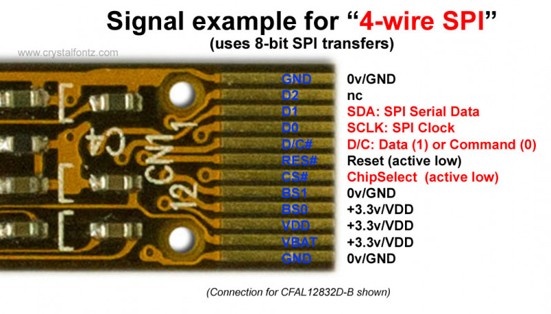
4-Wire SPI
In a typical “4-wire SPI” LCD/OLED application the connections will be:
- SCK: the SPI ClocK, as usual
- SS: the Slave Select, often labeled as CS – – Chip Select
- MOSI: the data from the master to the display, usually labeled as SDA (Serial DAta)
- C/D: Command /Data
Now you should have been expecting the fourth line to be MISO, so you could read data back from the display–but with LCD controllers, there is a twist.
We need some history to understand the 4th line as used in SPI displays. Traditionally, parallel interface LCD controllers had two registers, a Command register and a Data register. You would write the command to the Command register, then write the appropriate data to the Data register. To select between them, there was a C/D (or A0) line. Set the line to 1=Command or 0=Data then the write the 8 bits of data.
Now back to “4-wire SPI,” the 4th wire is “C/D.” So you can either make an 8-bit SPI write to the display controller’s Command register or an 8-bit SPI write its Data register depending on the state of the C/D line.
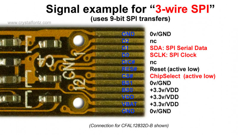
3-Wire SPI
In a typical “3-wire SPI” LCD/OLED application the connections will be:
- SCK: the SPI clock, as usual
- SS: the Slave Select, often labeled as CS – – Chip Select
- MOSI: the data from the master to the display, usually labeled as SDA (Serial DAta)
When does a “3-wire SPI” actually use 4 wires?
There are some controllers that use the “3-wire SPI” transfer format (encoding C/D and R/W as additional bits in the SPI transfer), but also have a MISO pin that can be used for reading data back from the display. So these displays use 4 physical wires, but have the a data encoding similar to the “3-wire SPI”.
Choosing Between a 4-Wire and 3-Wire SPI
Initially, “3-wire SPI” seems like a better solution, less wires, same function, what is there not to like? Well, the same history that gave us the extra C/D line now gives us an extra C/D bit–instead of using 8-bit transfers, “3-wire SPI” uses 9-bit (!) transfers.
If you are using software and GPIO to implement the SPI master, then it is no problem to modify the code to make it transfer 9 bits at a time. However, making 9-bit transfer with SPI hardware implementations may be difficult or impossible. Some of the newer and more innovative processors have more flexible hardware SPI implementations that may allow 9-bit transfers.
SPI (Serial Peripheral Interface) is popular for daisy-chaining devices because of its simple, shift-register-like architecture and high-speed synchronous signaling. Here’s why it works well:
Shift Register Architecture
-
Many SPI devices (like DACs, LED drivers, or shift registers) act like cascaded shift registers.
-
Each device passes along incoming data to the next in the chain via its MISO → MOSI connection.
-
After the master clocks in enough bits (one device’s worth × number of devices), each device latches the data relevant to it when the chip-select (CS) is toggled.
This makes it possible to address all devices in the chain with one continuous stream of bits. Making “Daisy-Chaining” devices trivial.
Trade-offs / Limitations
-
Latency grows with chain length, since you must clock through all devices to update one.
-
Not all SPI devices support daisy-chaining; the device must forward unused bits to the next device.
-
Debugging chains can be harder if one device in the middle fails.
-
Some systems may still prefer separate CS lines if random-access updates are needed.
One More Thing About SPI LCD and OLED Display Controllers
There is another non-SPI-standard thing that some SPI display controllers do, and that is they use their single data line bidirectionally–for both writing and reading. Typically, you would write the “read command” bits, then make the data line an input, then read back some number of bits from the display. Some controllers go a bit (sorry) further and encode the traditional Read/Write line from the old parallel interface into a 10th R/W bit. These use a 10-bit SPI transfer, with a bi-directional data line.
In Summary
Each LCD/OLED controller IC that supports SPI will include its specific SPI transfer format and list the formats for its read and write commands. You will want to look at the format of the controller’s SPI interface and evaluate whether you can use the hardware SPI Master that is part of your microcontroller, or if you need to write your own software SPI master.
Questions?
If you have any questions, please contact our knowledgeable and friendly support staff by email, phone, or chat.