
Transparent OLED on Raspberry Pi
One of our most frequently asked questions is “Can I use the transparent OLED with a Raspberry Pi?” The answer is a resounding Yes!
The transparent OLED can be driven by the GPIO pins of the RPi. And even better? It’s really quite simple!
How To Use a Raspberry Pi to Run a Transparent Display
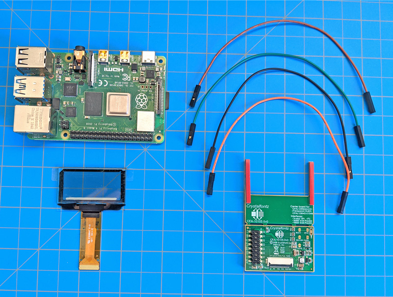
First, you’ll need:
- Raspberry Pi
- Transparent OLED Display
- Transparent OLED Breakout Board
- 4 Jumper Wires
- Soldering iron
Reference Docs:
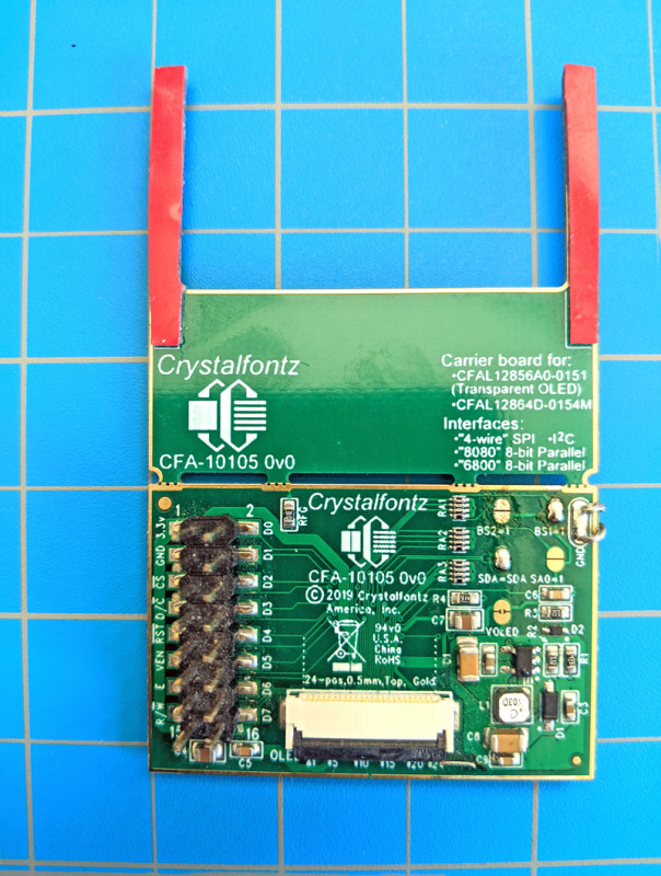
Step 1: Close Jumpers to Convert to I2C
Use solder to close BS1=1 and SDA=SDA.
On the right side of the breakout board there is a group of five jumpers. To set the board up to communicate using I2C two of the jumpers need to be closed. You can see that we have simply blobbed some solder to close the two jumpers. This is an engineering sample board, so it’s not as clean as you might hope.
As described on the back of the board, and in the board’s datasheet, the interface selection for I2C is BS1=1 and BS2=0. The breakout board also handles tying D1 and D2 together to serve as SDA when the jumper SDA=SDA is closed.
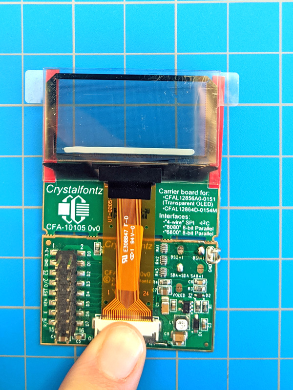
Step 2: Connect the Transparent Display
Insert the display tail into the ZIF connector and close the connector
With the shiny pins facing up, gently slide the tail of the display into the ZIF connector. As the name implies, the tail should go into the connector with Zero Insertion Force.
Once the tail is well seated in the connector, close the connector by pressing down on the black hinge.
This would also be a good time to tape the display to the board, if desired. Simply peel the tape backing off, align the display, and press gently down to secure the display.
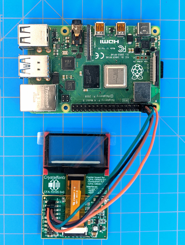
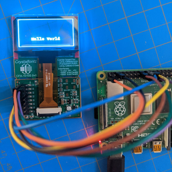
Step 3: Wire the Breakout Board to the Raspberry Pi
Connect Power, Ground, SLC and SDA
Just four wires are needed to wire the transparent display to the RPi.
- Power: The orange wire goes from the 3.3v pin on the breakout board to the 3.3v power on the RPi. We used Pin 1, but any of the 3.3v power pins will work.
- Ground: The black wire goes from GND on the breakout board to pin 6 ground on the RPi.
- SCL: The brown wire goes from D0 (SCL) to pin 5 (GPIO 3 (I2C Clock)) on the RPi.
- SDA: The green wire goes from D1 (SDA) to pin 3 (GPIO 2 (I2C Data)) on the RPi. Or, if you’re feeling weird, you can connect to D2, since the jumper SDA=SDA is closed tying D1 and D2 together.
The RPi has internal pull ups for the I2C pins, so there’s no need to use external pull ups.
Step 4: Install the latest version of luma.OLED
First, make sure I2C is enabled on your Raspberry Pi. You can follow this tutorial to enable it.
We’re going to use the Luma OLED library to get this display up and running. This command will install the latest version:
$ sudo -H pip3 install --upgrade luma.oledYou also need to give them permission to access some hardware interfaces, where “pi” is the name of the account you’ll be using (the default is “pi”).
$ sudo usermod -a -G spi,gpio,i2c piIf you need help troubleshooting visit their explainer on how to install.
Step 5: Display Something on Your Transparent OLED
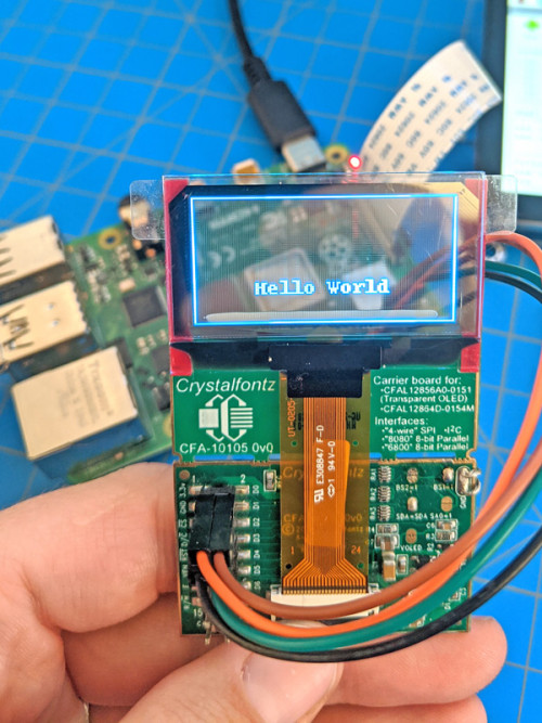
The code below will give you a hello world, just run it on the RPi.
It’s really that simple!
Luma.OLED has a whole host of examples that can be downloaded from their github.
from luma.core.interface.serial import i2c
from luma.core.render import canvas
from luma.oled.device import ssd1309

serial = i2c(port=1, address=0x3C)
device = ssd1309(serial)

with canvas(device) as draw:
    draw.rectangle(device.bounding_box, outline="white", fill="black")
    draw.text((30, 40), "Hello World", fill="white")
I Don’t Have a Soldering Iron (or want to use SPI)
That’s fine! You can use SPI.
If changing the interface on the breakout board isn’t an option, change the code to use SPI instead. Make sure SPI is enabled on your Pi. Then import “spi” instead of “i2c” and define serial as “spi(device=0,port=0)”.
You’ll also need to change the wiring a bit. Luma’s documentation includes a nice SPI wiring table, though you’ll ignore the pin numbers for the display. It’s also nice to look at the Raspberry Pi pinout to remember that GPIO numbers are not the same as the pin numbers on the RPi.
Bringing up Other OLEDs on Raspberry Pi
This tutorial can be followed exactly for our three OLEDs that pair with the CFA10105 breakout board: the transparent OLED, a white OLED, and a yellow OLED.
The luma.OLED library interfaces with many OLED controllers (SSD1306, SSD1309, SSD1322, SSD1325, SSD1327, SSD1331, SSD1351, SSD1362, SH1106, and WS0010), so with a few adjustments (changing the device define to match your display’s controller, and having a compatible breakout board) this tutorial can be used for many of our OLED displays.
Bonus good news on the breakout board front! This generic breakout board simplifies creating a breakout board for any display.
Contact Us
If you have any questions, reach out to support@crystalfontz.com. We also provide chat and telephone support Monday through Friday during our open hours.
We love to hear about your projects! If you bring up a transparent OLED on raspberry pi, let us know! Find us around the web (YouTube, Facebook, Instagram, LinkedIn, Twitter, Forum) and let us know what you’re working on.
Join us discussing this project in our forum.

Kelsey is an engineer at Crystalfontz. She graduated from Gonzaga University with a BS in Electrical Engineering. Kelsey’s roles at Crystalfontz include product design, custom parts, customer support, documentation, and product demonstrations.
What our customers say about Kelsey:
“As a new user to the world of LCD electronics, Kelsey has been a Godsend in providing the hand-holding I needed to get my project up and running despite my own efforts at fouling things up! :-)” – Owen M
“Kelsey got me through changing code for a new LCD in only two short emails.” – Phillip V
“The agent that I talked with (Kelsey), is technically sound and she knows what she is doing. The support is what made my job easier to get started with the different display technologies. Thank you!” – Vatsal S