Tiny OLED Full Color Slideshow
This guide will walk through how to get started with one of our small full color OLED displays. Then, we’ll talk about a super quick and easy project to do with this display – a photo slideshow!
The display we’ll be using is a 0.96″ full color OLED. We have two versions of this display, both of which use the SSD1331 OLED controller. The instructions will work for both the CFAL9664B1 and CFAL9664B2 OLED displays with breakout board.
These displays are extremely similar – the only noticeable differences are the panel voltage requirement and slightly different initialization settings. With the breakout board, the panel voltage is taken care of for you! The board also transforms the more challenging solder down tail into a convenient 0.1″ header compatible with jumper cables and breadboards.
What You’ll Need
While this display is available as a stand alone part, unless you have access to a hot bar soldering machine, or really like fine pitch soldering, we recommend buying the display and breakout board together. If you’re new to electronics, the complete Full Color OLED Seeeduino Development Kit will have just about everything you need.
For the first part of the tutorial – Getting Started with the Full Color OLED you’ll need:
- the display and breakout board
- an Arduino compatible 3.3v logic microcontroller (Seeeduino)
- a USB cable
- the Arduino IDE (or other IDE for modifying and loading the code)
- the demo code
- and jumper wires.
For the second part of the tutorial – Full Color OLED Slideshow, you’ll also need:
- an SD card
- an SD card breakout board
- MS Paint (or other program that can save images as 24-bit BMP)
- and the images you want to display
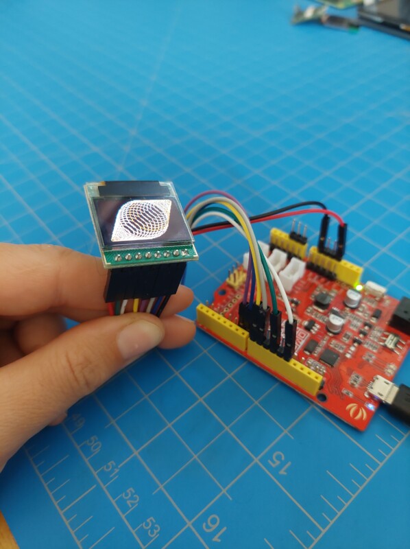
Part 1: Getting Started with the Full Color OLED
First, we’ll just get the OLED wired up and running the standard demonstration code.
The demo code can be found on Github. Download the code, and scroll down to where the demonstrations are turned on and off. Select which ever demos you’d like to run, but for now leave bmpdemo set to 0.
//============================================================================
// Main Loop
//
// Set/Clear the defines to run a particular demo
// SD must be connected in order for BmpDemo to work
//============================================================================
#define gammagradientdemo 1
#define colorbarsdemo     0
#define tractordemo       0
#define filldemo          1
#define cheesylinesdemo   1
#define checkerdemo       1
#define circledemo        1
#define bmpdemo           0
#define waittime          1000
Then upload the code to your seeeduino. We upload the code before connecting the display to the controller to make sure the code on the seeeduino does not cause damage to the display.
Also, if you’re using a switchable seeeduino, make sure the voltage is set to 3.3v rather than 5v to avoid damaging the display.
The breakout board makes this quite simple by breaking the tail out to eight labeled 0.1″ header pins. Use the table below or the picture above to make your connections. Make sure you have disconnected the power from the seeeduino before wiring the display.
| Breakout Board | Color | Seeeduino |
| GND | Black | GND |
| EN_VP | Blue | D7 |
| CS | Grey | D9 |
| RST | Purple | D6 |
| D/C | Yellow | D8 |
| SCK | White | D13 |
| MOSI | Green | D11 |
| +3.3v | Red | 3.3v |
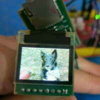
With the wiring done and the demo code loaded, all that remains is to apply power. The display should begin to loop through a series of demonstrations.
Part 2: Full Color OLED Slideshow
Prepare Slideshow Images
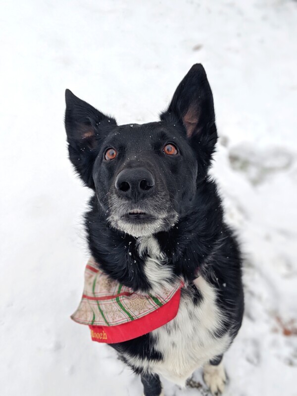
An important thing to remember in selecting photos for your slideshow is that this display is only 96×64 pixels. That means there’s a limited amount of information that we’ll be able to display.
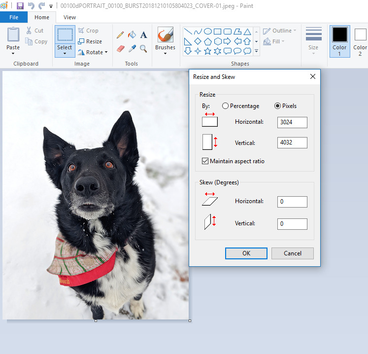
Unedited, this picture of my dog is ~3000×4000 pixels. Obviously, this is much too large to be displayed on our OLED.
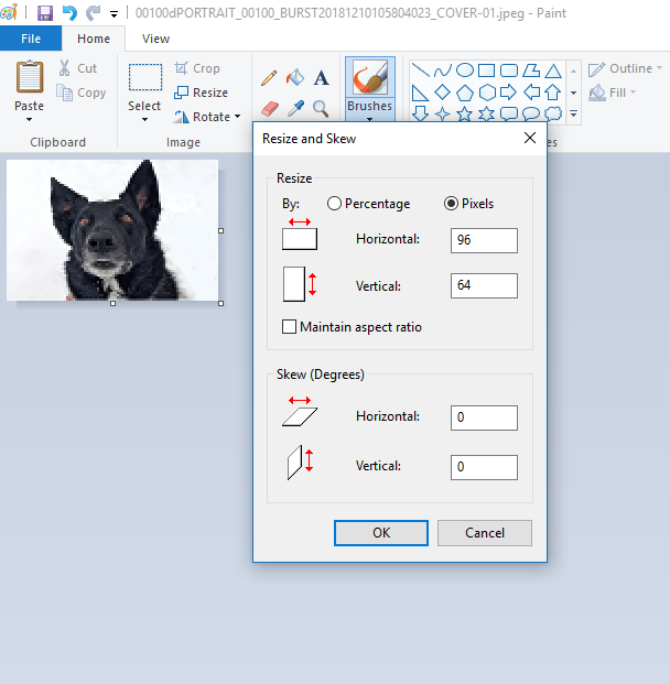
That means the first step is to crop the photo to an appropriate shape and then reduce the size. Obviously, you can do this with whatever program you want, but MS Paint works.
When selecting your photos, remember the low pixel density. What you’ll end up with is something more akin to pixel art than the high definition photos we’re used to, but certainly still recognizable.

Save your photo as a 24-bit BMP. This is the default BMP size in Paint, but if you use a different program it may default to a different color depth. The final image should be 18,486 bytes. A BMP header is 54 bytes, plus 3 bytes per pixel (24-bit color means 3 bytes of color data per pixel, one each for red, green, and blue).
54(header)+3(colors)x96x64(pixels) = 18,486
Save the image to a uSD card and repeat for as many images as you’d like.
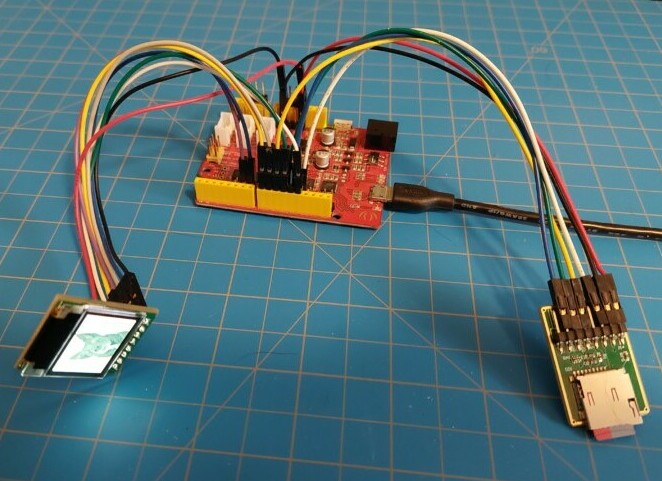
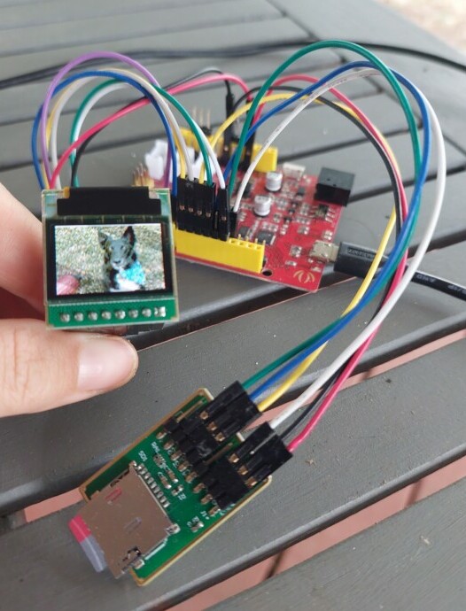
Connect uSD Card Reader
Connecting the uSD card breakout board is nice and easy. The code assigns it its own chip select pin (pin 10), and other than that, it uses the same connections as the display.
| uSD Breakout Board | Color | Seeeduino |
| Power | Red | 3.3v |
| GND | Black | GND |
| SCK | White | D13 |
| CS | Yellow | D10 |
| MISO | Blue | D12 |
| MOSI | Green | D11 |
The provided demo code includes a show BMP routine. For our photo slideshow, only this option should be selected. Going back to the defines, we’ll set it up to only do the BMP routine:
//============================================================================
// Main Loop
//
// Set/Clear the defines to run a particular demo
// SD must be connected in order for BmpDemo to work
//============================================================================
#define gammagradientdemo 0
#define colorbarsdemo     0
#define tractordemo       0
#define filldemo          0
#define cheesylinesdemo   0
#define checkerdemo       0
#define circledemo        0
#define bmpdemo           1
#define waittime          1000
For your final implementation, you can slim the code down by quite a bit, only reserving the routines needed to initialize the display and show the BMPs. Also, a case or box would be nice, but we’ll leave the style to you!
Want to see another cool project? Check out these Transparent OLED glasses.
Contact Us
If you have any questions, we can be reached at support@crystalfontz.com, we also provide chat and telephone support Monday through Friday during our open hours.
We love to hear about your projects! Find us around the web (YouTube, Facebook, Instagram, LinkedIn, Twitter, Forum) and let us know what you’re working on.
Kelsey is an engineer at Crystalfontz. She graduated from Gonzaga University with a BS in Electrical Engineering. Kelsey’s roles at Crystalfontz include product design, custom parts, customer support, documentation, and product demonstrations.
What our customers say about Kelsey:
“As a new user to the world of LCD electronics, Kelsey has been a Godsend in providing the hand-holding I needed to get my project up and running despite my own efforts at fouling things up! :-)” – Owen M
“Kelsey got me through changing code for a new LCD in only two short emails.” – Phillip V
“The agent that I talked with (Kelsey), is technically sound and she knows what she is doing. The support is what made my job easier to get started with the different display technologies. Thank you!” – Vatsal S