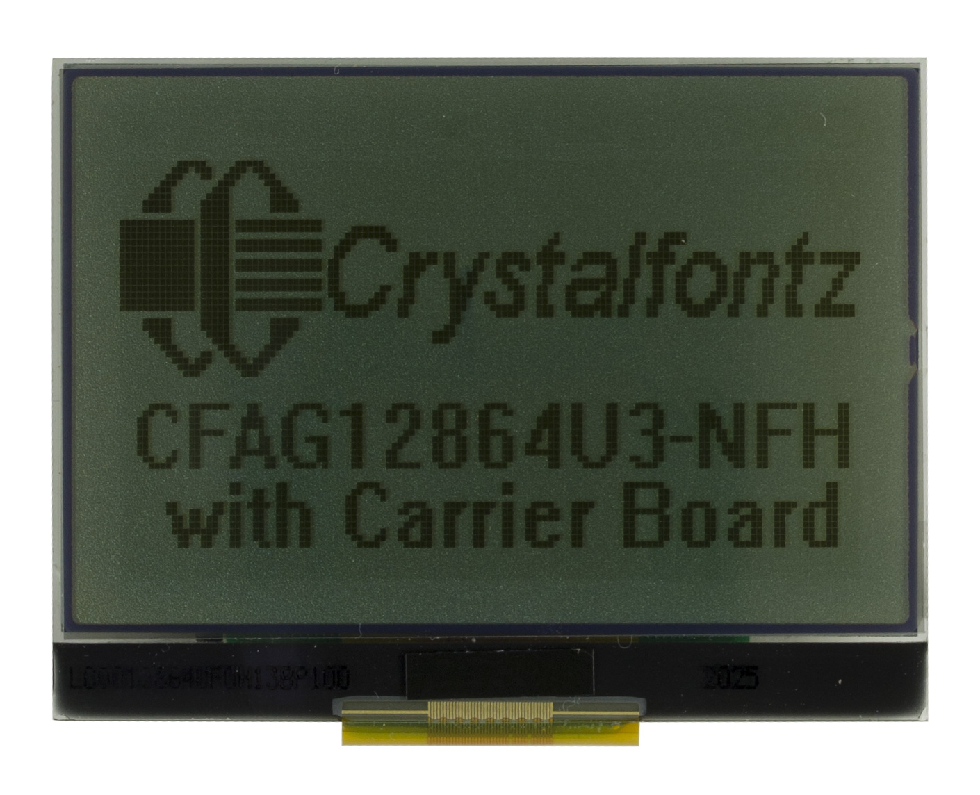
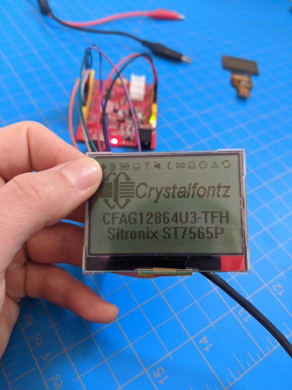
At 2.2" diagonal, this transflective display is big enough to get all the information across. Plus, it's readable in most lighting environments, from indoor light to direct sunlight. If you're looking for a display that can be read in low-light situations, check out the backlight version of this display. This display has a 128x64 monochrome array, plus a row of addressed icons along the top edge of the display.
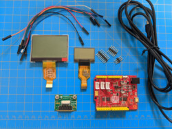
The included adapter board simplifies integrating the display into a product or bringing up a demonstration of the display. The board breaks the ZIF tail out into a 16-position 0.1" header. This makes wiring the display simple and solder-free. The 2x2-56 threaded standoffs on the adapter board enable the entire assembly to be mounted into a final design.
Home » Graphic LCD Adapter Board: CFA10110 Getting Started
Relevant Displays and Kits
Do you need help getting started with your graphic LCD and CFA10110 adapter board? This getting started guide helps bring up any of the following displays or kits:
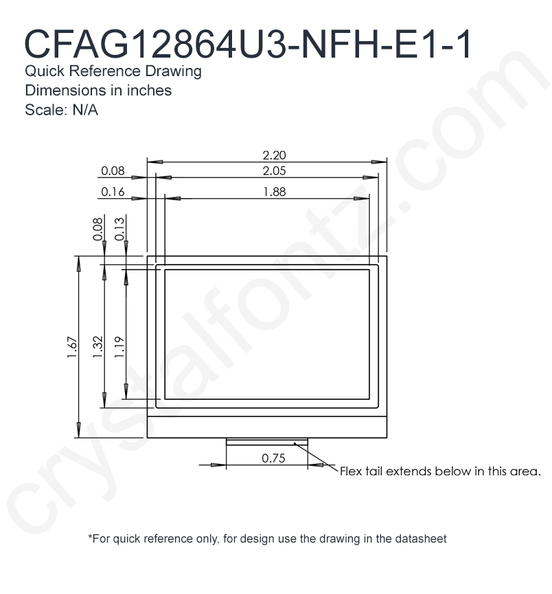
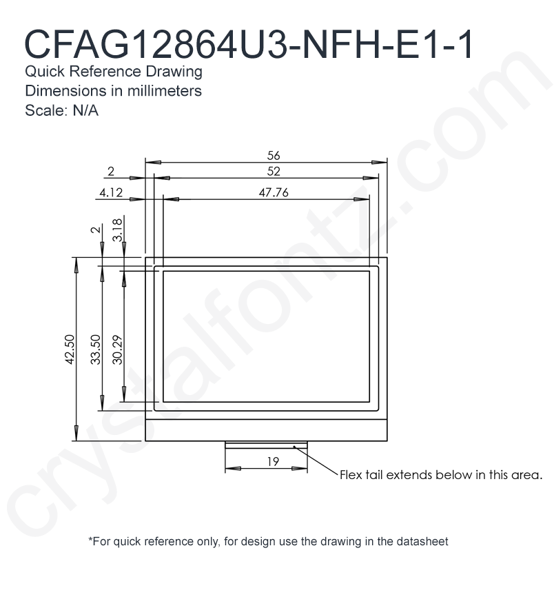
The family of U3 and T3 monochrome graphic LCD displays are great because they’re low power, thin, easily readable, and quick to develop with. The U4 and T4 have the added bonus of being transparent! The U family is 2.2″ on the diagonal, while the Ts are 1.1″. Versions with “TFH” in the part number include a frame backlight that makes these displays readable in dark environments while the “NFH” displays are reflective and rely on external light sources. “NFI” means no backlight and transparent.
These graphic LCDs are a great way to provide low-fuss information in a project. They can display any shape you want, so no worrying about an included font table not including necessary characters. Plus, they’re quicker to develop for than a full color TFT display. They have extremely low power requirements, especially if the backlight is selectively used. They can even be converted to create a DIY transparent display.
We designed the CFA10110 adapter board for these displays to further simplify incorporating these displays. The board breaks the tail out to a 16-pin 0.1″ header, so no soldering is necessary to connect to the display. Further, 2 x 2-56 threaded mounting standoffs make securing this display module a breeze. And jumpers on the board handle switching between SPI and parallel interfaces.
Getting Started
This guide will walk through setting up the display with a CFA10110 in SPI mode. Wiring information for the parallel modes can be found in the datasheets available in the datasheet tab of the product pages or in the demo code.
This is the contents of any of the above Development Kits.
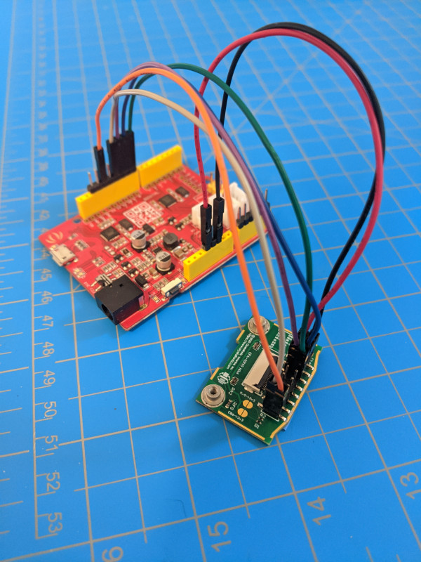
Wire the Board to your Microcontroller:
Using the jumper wires, connect the CFA10110 board to the microcontroller. We’re using an Arduino clone, thus “ARD”.
// ARD    | LCD  | Color
// ---------+--------+-------
// 3v3    | 3v3  |  Red
// GND    | GND  |  Black
// D8     | DC   |  Green
// D9     | RES  |  Blue
// D10    | CS   |  Purple
// D11    | D7   |  Gray
// D13    | D6   |  Orange
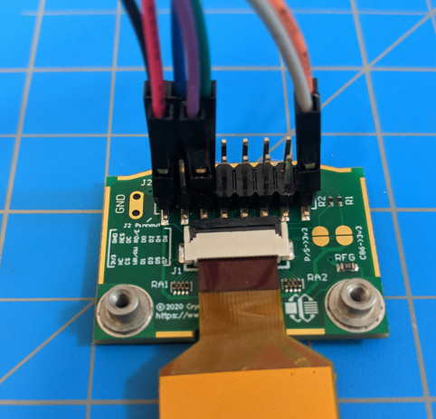
Connect the Display to the Adapter Board
If you ordered a kit or display module ending in E1-1 or E1-2, you can skip this step. We did this for you.
If you ordered the CFA10110 separately from the display, insert the tail of the display shiny pins down into the ZIF connector. You shouldn’t need a lot of force to insert the tail into the connector (thus “Zero Insertion Force”).
Once the tail is firmly seated into the connector, close the connector by pushing down on the black tab.
Run A Sketch
The final step is to run a sketch. Connect your controller to your computer with the USB cable and upload your sketch. If you’re using our sketch, check that the display defined in LCD_low.h is the same as the display you just wired up. It changes the contrast and a few other settings and can make the display difficult to read if the wrong one is defined. The section that needs to be checked looks like this:
To use a U3 display, simply switch the 1 and 0 and change “#define display_type CFAG12864T3” to “#define display_type CFAG12864U3”
The code uses some different names for the pins than are written on the board. Here’s a copy the table from the code with a column listing the names from the code and the pin names from the CFA10110:
Use the Backlight
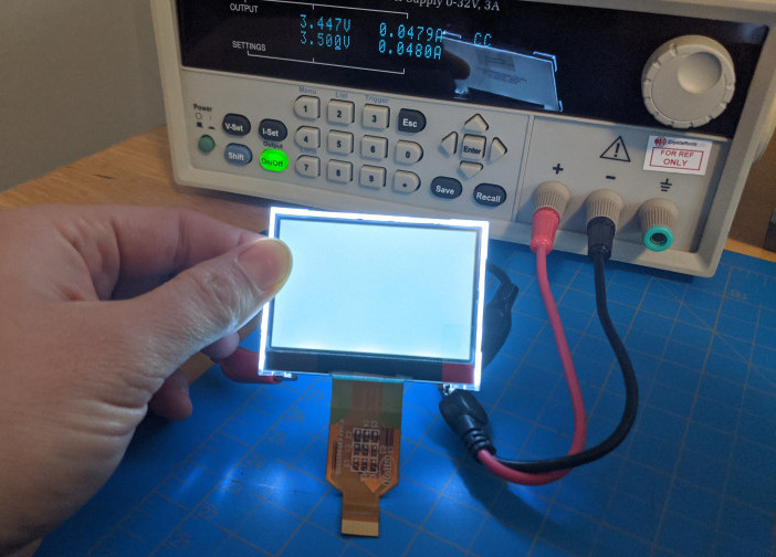
For the modules that include a backlight, connect a power source to the A and K tabs on the backlight frame. Check the datasheet of the module to ensure you provide the correct backlight voltage and current. The T3 module requires less power than the U3 module.
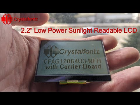
Video
If you want to see any of these steps performed, check out the video:
If you have any questions, we can be reached at support@crystalfontz.com, we also provide chat and telephone support Monday through Friday during our open hours.
Kelsey is an engineer at Crystalfontz. She graduated from Gonzaga University with a BS in Electrical Engineering. Kelsey’s roles at Crystalfontz include customer support, documentation, product demonstrations, and design.
What our customers say about Kelsey:
“As a new user to the world of LCD electronics, Kelsey has been a Godsend in providing the hand-holding I needed to get my project up and running despite my own efforts at fouling things up! :-)” – Owen M
“Kelsey got me through changing code for a new LCD in only two short emails.” – Phillip V
“The agent that I talked with (Kelsey), is technically sound and she knows what she is doing. The support is what made my job easier to get started with the different display technologies. Thank you!” – Vatsal S


.")
.")